introduction
this is a tiny project i've been working for some time.
the purpose is to gather temperature information from two sources: inside my room and outside. the information is stored in a log file every minute and then make a plot of that information.
equipment
- Arduino UNO WiFi REV2;
- 2 pcs. × DS18B20 - Programmable Resolution 1-Wire Digital Thermometer;
- 2 pcs. × 4,75 kΩ resistor;
- 1 pcs. × RND 205-01147 - M8 Cable Connector, 2m, Straight, Socket, 4 Poles, A-Coded, Solder, RND Connect;
- 1 pcs. × RND 205-01150 - M8 Cable Connector, 5m, Straight, Socket, 4 Poles, A-Coded, Solder, RND Connect;
- 2 pcs. × RND 205-01133 - M8 Straight Plug Circular Sensor Connector, 4 Poles, A-Coded, Solder, RND Connect;
- 1 pcs. × BBMM-10-Q1RD - Jumper Wire, Male to Male, 10 ST, 150 mm, multicoloured, RND Components;
- Server with Linux operating system;
- 3D printer
testing the concept
using a breadboard and single sensor i've managed to test it. there's a lot of tutorial in the internet about connecting DS18B20 to an arduino.
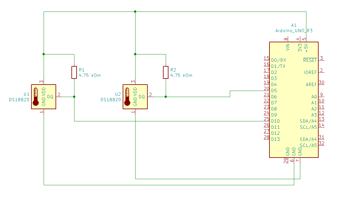
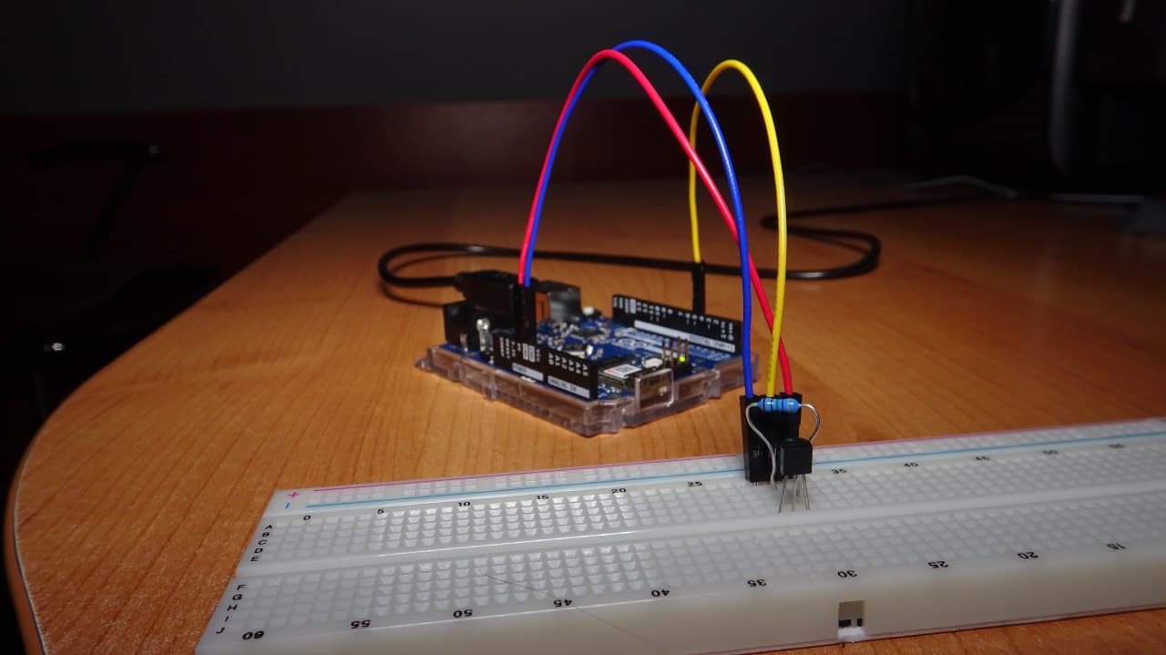
these tutorials are usually for arduinos without wifi, so i had to modify it slightly:
/*
WiFi Web Server
A simple web server that shows the value of the analog input pins.
This example is written for a network using WPA encryption. For
WEP or WPA, change the Wifi.begin() call accordingly.
Circuit:
* Analog inputs attached to pins A0 through A5 (optional)
created 13 July 2010
by dlf (Metodo2 srl)
modified 31 May 2012
by Tom Igoe
*/
#include
#include
#include "arduino_secrets.h"
///////please enter your sensitive data in the Secret tab/arduino_secrets.h
char ssid[] = SECRET_SSID; // your network SSID (name)
char pass[] = SECRET_PASS; // your network password (use for WPA, or use as key for WEP)
int keyIndex = 0; // your network key Index number (needed only for WEP)
int status = WL_IDLE_STATUS;
WiFiServer server(80);
#include
#include
// Data wire is plugged into pin 2 on the Arduino
#define ONE_WIRE_BUS1 5
#define ONE_WIRE_BUS2 10
// Setup a oneWire instance to communicate with any OneWire devices
// (not just Maxim/Dallas temperature ICs)
OneWire oneWire1(ONE_WIRE_BUS1);
OneWire oneWire2(ONE_WIRE_BUS2);
// Pass our oneWire reference to Dallas Temperature.
DallasTemperature sensor1(&oneWire1);
DallasTemperature sensor2(&oneWire2);
void setup() {
//Initialize serial and wait for port to open:
Serial.begin(9600);
while (!Serial) {
; // wait for serial port to connect. Needed for native USB port only
}
Serial.println("Initialization...");
// Power for the second sensor
pinMode(2, OUTPUT);
digitalWrite(2, HIGH);
// check for the WiFi module:
if (WiFi.status() == WL_NO_MODULE) {
Serial.println("Communication with WiFi module failed!");
// don't continue
while (true);
}
String fv = WiFi.firmwareVersion();
if (fv < WIFI_FIRMWARE_LATEST_VERSION) {
Serial.println("Please upgrade the firmware");
}
// Start up the library
delay(500);
sensor1.begin();
sensor2.begin();
// attempt to connect to Wifi network:
while (status != WL_CONNECTED) {
Serial.print("Attempting to connect to SSID: ");
Serial.println(ssid);
// Connect to WPA/WPA2 network. Change this line if using open or WEP network:
status = WiFi.begin(ssid, pass);
// wait 10 seconds for connection:
delay(10000);
}
server.begin();
// you're connected now, so print out the status:
printWifiStatus();
}
void loop() {
// listen for incoming clients
WiFiClient client = server.available();
if (client) { // if you get a client,
Serial.println("new client"); // print a message out the serial port
String currentLine = ""; // make a String to hold incoming data from the client
String getLine = "";
while (client.connected()) { // loop while the client's connected
if (client.available()) { // if there's bytes to read from the client,
char c = client.read(); // read a byte, then
//Serial.write(c); // print it out the serial monitor
if (c == '\n') { // if the byte is a newline character
// if the current line is blank, you got two newline characters in a row.
// that's the end of the client HTTP request, so send a response:
if (currentLine.length() == 0) {
// Check to see if the client request was "GET /H" or "GET /L":
if (getLine.startsWith("GET /H")) {
digitalWrite(LED_BUILTIN, HIGH); // GET /H turns the LED on
goto default_page;
}
else if (getLine.startsWith("GET /L")) {
digitalWrite(LED_BUILTIN, LOW); // GET /L turns the LED off
goto default_page;
}
else if (getLine.startsWith("GET /ds18b20")) {
// HTTP headers always start with a response code (e.g. HTTP/1.1 200 OK)
// and a content-type so the client knows what's coming, then a blank line:
client.println("HTTP/1.1 200 OK");
client.println("Content-type: text/html");
client.println();
// call sensors.requestTemperatures() to issue a global temperature
// request to all devices on the bus
sensor1.requestTemperatures(); // Send the command to get temperatures
client.print(sensor1.getTempCByIndex(0)); // Why "byIndex"?
client.print(" ");
sensor2.requestTemperatures(); // Send the command to get temperatures
client.print(sensor2.getTempCByIndex(0)); // Why "byIndex"?
// You can have more than one IC on the same bus.
// 0 refers to the first IC on the wire
// The HTTP response ends with another blank line:
client.println();
}
else {
default_page:
// HTTP headers always start with a response code (e.g. HTTP/1.1 200 OK)
// and a content-type so the client knows what's coming, then a blank line:
client.println("HTTP/1.1 200 OK");
client.println("Content-type: text/html");
client.println();
// the content of the HTTP response follows the header:
client.print("Status of the LED: ");
client.print( digitalRead(LED_BUILTIN) ? "ON" : "OFF" );
client.print( " " );
client.print("Click here turn the LED on pin 9 on");
client.print("Click here turn the LED on pin 9 off");
// output the value of each analog input pin
for (int analogChannel = 0; analogChannel < 6; analogChannel++) {
int sensorReading = analogRead(analogChannel);
client.print("analog input ");
client.print(analogChannel);
client.print(" is ");
client.print(sensorReading);
client.println(" ");
}
client.println(" ");
// call sensors.requestTemperatures() to issue a global temperature
// request to all devices on the bus
sensor1.requestTemperatures(); // Send the command to get temperatures
sensor2.requestTemperatures(); // Send the command to get temperatures
client.print("Temperature1 is: ");
client.print(sensor1.getTempCByIndex(0)); // Why "byIndex"?
client.println(" ");
client.print("Temperature2 is: ");
client.print(sensor2.getTempCByIndex(0)); // Why "byIndex"?
// You can have more than one IC on the same bus.
// 0 refers to the first IC on the wire
client.print("° C.");
// The HTTP response ends with another blank line:
client.println();
}
// break out of the while loop:
break;
} else { // if you got a newline, then clear currentLine:
if (currentLine.startsWith("GET /")) {
getLine = currentLine;
}
Serial.println( currentLine );
currentLine = "";
}
} else if (c != '\r') { // if you got anything else but a carriage return character,
currentLine += c; // add it to the end of the currentLine
}
}
}
// give the web browser time to receive the data
delay(1);
// close the connection:
client.stop();
Serial.println("client disonnected");
}
}
void printWifiStatus() {
// print the SSID of the network you're attached to:
Serial.print("SSID: ");
Serial.println(WiFi.SSID());
// print your board's IP address:
IPAddress ip = WiFi.localIP();
Serial.print("IP Address: ");
Serial.println(ip);
// print the received signal strength:
long rssi = WiFi.RSSI();
Serial.print("signal strength (RSSI):");
Serial.print(rssi);
Serial.println(" dBm");
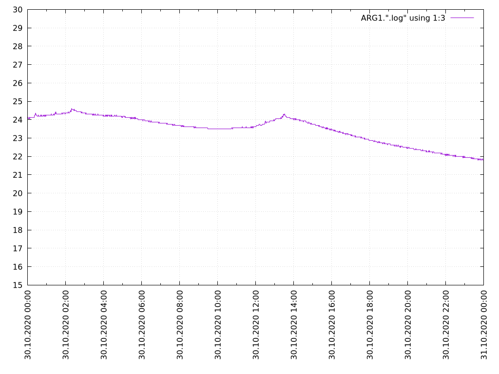
}i used gnuplot to draw plot of the data:
set xdata time
set format x "%d.%m.%Y\ %H:%M"
set timefmt "%d.%m.%Y\ %H:%M:%S"
set xtics 7200 rotate by 90 textcolor rgb "#000000" right

set ytics 1 nomirror
set yrange [15:30]

set grid xtics ytics
show grid

plot ARG1.".log"  using 1:3 with lines

pause -1
here's what i get:
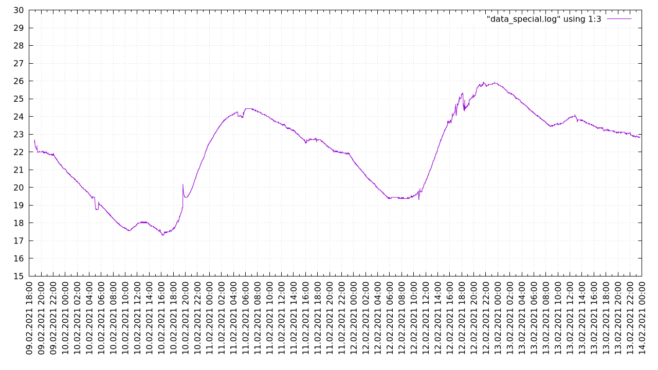
it is possible to combine data for several days and get this:
enclosure
i'm only familiar with Blender. it is not a convenient tool to make such enclosures, because it is not parametric. should try to learning using FreeCAD instead.
the first try failed. hole for power supply is misaligned, cover didn't had sides - it was completely flat, and holes for sensor sockets were wrong, so i will show you the second version:
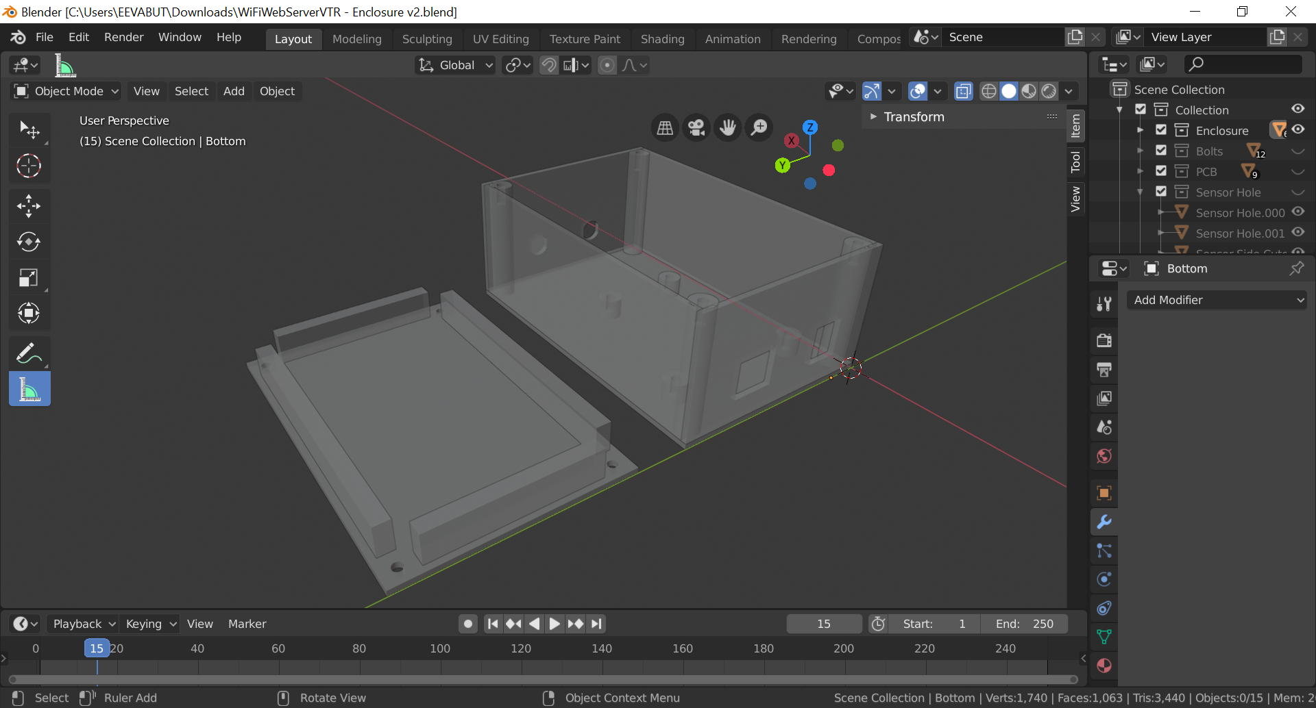
download the blender source file: https://pik-pik.ee/nextcloud/s/65BgY8SFFar2KWk.
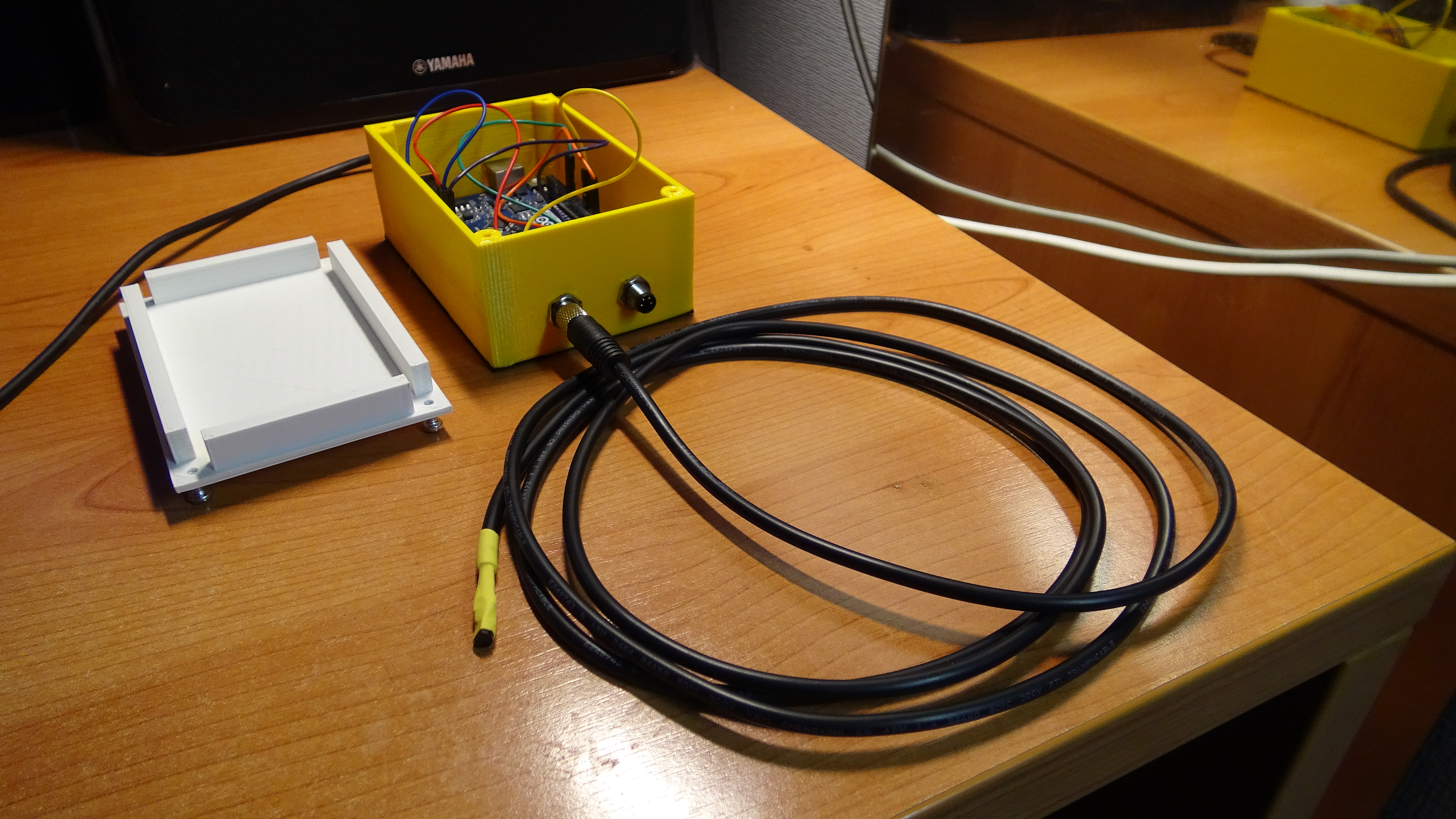
putting it all together
after several days of 3d printing, i put all the parts inside the box and they all fit perfectly.
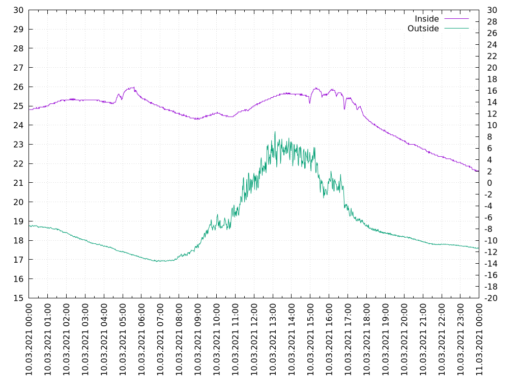
now i need to modify scripts slightly to display second data line on the plot:
#set term qt enhanced font "Latin Modern Roman, 12"
set term pngcairo enhanced color font "Latin Modern Roman, 12" size 1024,768
set output ARG1.".png"

set xdata time
set x2data time
set format x "%d.%m.%Y\ %H:%M"
set timefmt "%d.%m.%Y\ %H:%M:%S"
set xtics 3600 rotate by 90 textcolor rgb "#000000" right
set x2tics 3600 format ""

set ytics 1 nomirror
set y2tics 2
set yrange [15:30]
set y2range [-20:30]

set grid xtics ytics
show grid

plot ARG1.".log"  using 1:3 axis x1y1 with lines title "Inside", ARG1.".log" using 1:4 axis x2y2 with lines title "Outside"

pause -1
waiting several day to gather some data and get the picture:
i also made a multiple day version:
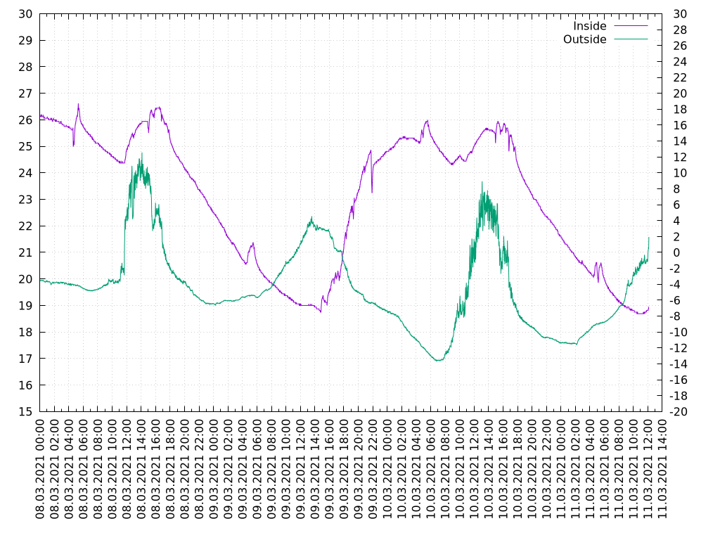
when the sun is shining the signal is a bit noisy. the problem is that my sensor on sunny side of the house. i need a longer cable to hide the sensor in a shadow.
all gathered data are available on following webpage: https://pik-pik.ee/temp/ .